The OSI Model, Part 1: Physical to Transport
Bits, frames, packets, segments. What each of the bottom four layers actually does, which device lives where, and the questions CompTIA uses to see if you really know the difference.
Every network you'll ever touch is moving data the same way: something at the top wants to send a message, and by the time it leaves the building it's a stream of voltage, light, or radio. The Open Systems Interconnection (OSI) model is the map of that trip, split into seven layers so people can talk about where something happens.
Nobody installs "OSI." The internet actually runs on the Transmission Control Protocol (TCP)/Internet Protocol (IP) suite. OSI is the shared vocabulary. When a senior tech says "that's a Layer 2 problem," they're telling you to stop looking at IP addresses and start looking at switches, Media Access Control (MAC) addresses, and Virtual Local Area Networks (VLANs). That vocabulary is exactly what Network+ tests.
This part covers the bottom four layers, the ones that move data. Part 2 covers Layers 5–7 and using the model to troubleshoot.
OSI isn't a named A+ objective, but you need the pieces: TCP vs. User Datagram Protocol (UDP) (1201 2.1) and what a switch does vs. a router (2.5). Knowing "switch = MAC address, router = IP address" covers most A+ questions.
Formal objective 1.1. Know every layer's number, name, Protocol Data Unit (PDU), devices, and protocols. Be able to place any device or symptom on a layer, and use layers to troubleshoot (5.1).
Layer 4 vs. Layer 7 firewalls (SY0-701 3.2), and knowing which layer an attack targets: Address Resolution Protocol (ARP) poisoning (L2), IP spoofing (L3), Synchronize (SYN) floods (L4).
Read layers directly out of a packet capture. Wireshark's detail pane is capture metadata followed by Layer 2, 3, and 4 headers: Frame, Ethernet II, Internet Protocol, TCP (CS0-004 1.3).
Prefer video first? Jump to the free videos ↓
The stack at a glance
Seven layers, numbered from the bottom. Data heading out travels down the stack, and each layer wraps it in its own header. That wrapping is called encapsulation. The receiver runs it in reverse, each layer peeling off its header on the way up.
Bottom to top: Please Do Not Throw Sausage Pizza Away. For the PDUs of Layers 1–4, top-down: Some People Fear Birds (Segments, Packets, Frames, Bits).
Physical
Layer 1 doesn't know what an address is. Its whole job is turning 1s and 0s into something that can cross a medium, and back again. That might be voltage on copper, pulses of light in fiber, or radio waves in the air. Layer 1 also defines the physical details: connector shapes, pin-outs, cable categories, signal timing, and how fast bits can go.
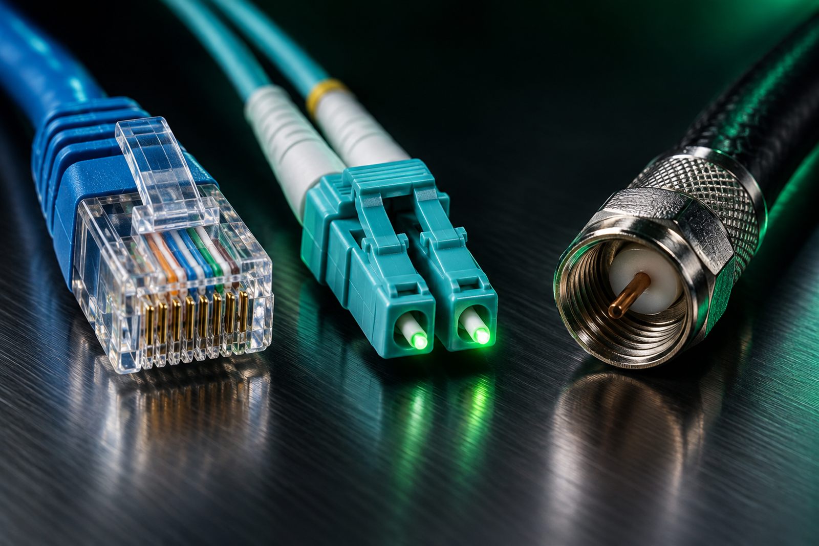 Registered Jack 45 (RJ45) · copperLucent Connector (LC) duplex · fiberF-type · coax
A hub is the classic Layer 1 device. It can't read anything. It takes the electrical signal coming in one port and repeats it out every other port. Everything plugged into a hub shares one collision domain, which is why hubs disappeared from real networks. They still show up on the exam as the wrong answer.
If a question mentions attenuation, crosstalk, a bad crimp, a wrong cable category, or a transceiver mismatch, it's a Layer 1 question even if it never says "Layer 1."
Data Link
Layer 2 delivers frames between devices on the same local network. It's the first layer with addresses, and those are MAC addresses: 48-bit link-layer addresses usually assigned by the manufacturer; software can override them, and Wi-Fi clients may use randomized addresses, written as six hex pairs like 3C:22:FB:9A:41:07.
The star of Layer 2 is the switch. Unlike a hub, a switch reads the source MAC of every frame it receives and records which port that address lives on in its MAC address table (also called the Content Addressable Memory (CAM) table). When a frame arrives, the switch looks up the destination MAC and sends it out only the right port. If it doesn't know the destination yet, it floods the frame out every port except the one it came in on, then learns from the reply.
Layer 2 also checks for damage. Every Ethernet frame ends with a Frame Check Sequence (FCS), a Cyclic Redundancy Check (CRC) value calculated over the frame. The receiver recalculates it, and if the numbers don't match, the frame is dropped. Ethernet detects errors; it doesn't fix them. Rising CRC counters on a switch port usually point back to a Layer 1 problem like a damaged cable or interference.
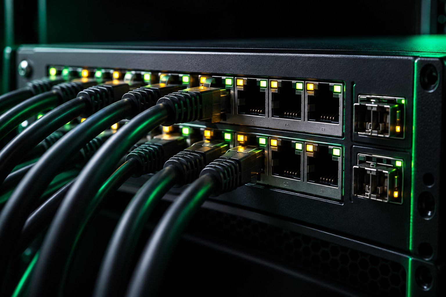
Collision domains vs. broadcast domains
This is one of the most-tested ideas in the bottom of the stack:
- Every switch port is its own collision domain. A hub is one big collision domain.
- A switch forwards broadcasts out all ports, so a switch (with no VLANs) is one broadcast domain.
- A router stops broadcasts. Each router interface is its own broadcast domain. VLANs split broadcast domains too.
Other Layer 2 residents: Network Interface Cards (NICs) (they own the MAC address), bridges, and wireless access points, which bridge wireless frames onto the wired network. Ethernet (802.3) and Wi-Fi (802.11) are both Layer 2 standards. 802.1Q VLAN tags live in the Layer 2 header; they get their own post under objective 2.2.
Network
Layer 2 gets a frame across one network. Layer 3 gets a packet across many of them. It uses logical addresses (Internet Protocol version 4 (IPv4) and Internet Protocol version 6 (IPv6)) that describe where a device is, and it decides the path a packet takes to get there. That decision is routing, and the device that makes it is the router, along with multilayer (Layer 3) switches.
The single most useful idea at Layer 3 is this: as a packet crosses routers, the IP addresses stay the same but the MAC addresses change at every hop. Each router strips the old frame, decides where the packet goes next, and builds a brand-new frame addressed to the next device's MAC.
Every IPv4 packet carries a time to live (TTL) value, and every router that forwards it subtracts one. When TTL hits zero, the router drops the packet and sends an ICMP "time exceeded" message back. That stops a packet from looping forever during a routing mistake, and it's exactly how tracert/traceroute maps a path.
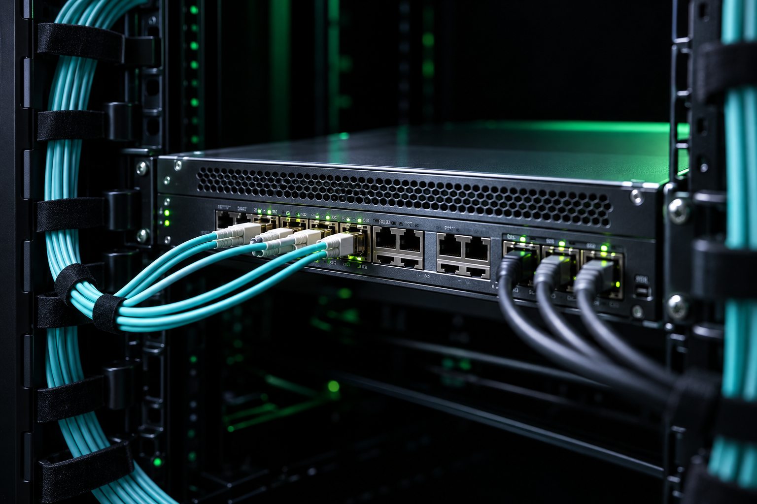
In the diagram, the source IP is a private address. In a real home or office, the edge router would translate it to a public address with Network Address Translation (NAT) before the packet hits the internet. NAT and Port Address Translation (PAT) are covered under objective 2.1.
ICMP also lives at Layer 3. It's the protocol behind ping, and it's how routers report errors. ICMP has no port numbers, which is a classic exam detail: ping doesn't use TCP or UDP at all.
Transport
Layer 3 gets the packet to the right computer. Layer 4 gets the data to the right application on that computer, using port numbers. An IP address plus a port, like 203.0.113.80:443, is called a socket.
| Port range | Name | Used for |
|---|---|---|
| 0–1023 | Well-known | Standard services: 22 Secure Shell (SSH), 53 Domain Name System (DNS), 443 Hypertext Transfer Protocol Secure (HTTPS) |
| 1024–49151 | Registered | Vendor services: 1433 Structured Query Language (SQL) Server, 3389 Remote Desktop Protocol (RDP) |
| 49152–65535 | Dynamic / ephemeral | Temporary client-side ports picked per connection |
Layer 4 has two main protocols, and the exam loves comparing them:
| TCP | UDP | |
|---|---|---|
| Connection | Connection-oriented: three-way handshake first | Connectionless: just sends |
| Reliability | Sequence numbers, acknowledgments, retransmits lost data | No acknowledgments, no retransmission |
| Flow control | Windowing adjusts how much is sent before an Acknowledgment (ACK) | None |
| Overhead | Higher (20+ byte header) | Lower (8 byte header) |
| Typical use | Web (Hypertext Transfer Protocol (HTTP)/HTTPS), SSH, email, file transfer | DNS queries, Dynamic Host Configuration Protocol (DHCP), Voice over Internet Protocol (VoIP), streaming, Trivial File Transfer Protocol (TFTP), Simple Network Management Protocol (SNMP), syslog |
| PDU name | Segment | Datagram |
The three-way handshake
Before TCP sends any data, the two sides agree on starting sequence numbers:
Connections end with a Finish (FIN) exchange (graceful close) or an Reset (RST) (abrupt reset). On Security+, a flood of SYNs that never complete the handshake is a SYN flood, a Layer 4 denial-of-service attack.
See it happen: encapsulation
Send a web request down the stack
Now see it in a real capture
Open a website, one packet at a time
Same browser as the stepper: 192.168.1.25 resolves a name, opens a TCP connection to 203.0.113.80:443, and pings it.
Packet list
| No. | Time | Source | Destination | Protocol | Length | Info |
|---|
Packet details
Packet bytes
The full Packet Explorer, the "Find the Needle" mission, and 100+ display filters live in the Pro Wireshark Filters guide.
Check yourself: which layer?
Put each item on its layer
Exam traps
- Hub vs. switch. Hub = Layer 1, repeats everything. Switch = Layer 2, forwards by MAC. A "multilayer switch" can also route at Layer 3.
- Access points are Layer 2. They bridge wireless frames to the wired network. They're not routers, even though your home "router" box contains one.
- Addresses map to layers. MAC = Layer 2. IP = Layer 3. Port = Layer 4. If the question names one, it's telling you the layer.
- Ping has no port. ICMP is Layer 3. Any answer that gives ping a TCP or UDP port is wrong.
- CRC errors start at the bottom. The FCS check happens at Layer 2, but the cause is usually Layer 1: cabling, interference, or a duplex mismatch.
- Routers split broadcast domains; switches split collision domains. Expect a "how many domains" question.
Field ticket: work it like a PBQ
"We moved my desk this morning. Now Outlook, Teams, and the shared drive all say offline. Everyone else on my team is fine." — J. Alvarez
Ethernet adapter Ethernet:

   Connection-specific DNS Suffix  . :
   Link-local IPv6 Address . . . . . : fe80::4c1d:9a2f:61b3:7e10%12
   Autoconfiguration IPv4 Address. . : 169.254.38.211
   Subnet Mask . . . . . . . . . . . : 255.255.0.0
   Default Gateway . . . . . . . . . :
GigabitEthernet1/0/14 is up, line protocol is up (connected)
  Description: ACCT-DESK-14
  Full-duplex, 100Mb/s, media type is 10/100/1000BaseTX
     18342 packets input, 2210417 bytes, 0 no buffer
     4812 input errors, 4797 CRC, 15 frame, 0 overrun
     0 runts, 0 giants

ACCT-SW1# ! same command, 60 seconds later
5136 input errors, 5121 CRC, 15 frame, 0 overrunWhere is the root cause?
What do you do first?
The cable is replaced. What proves the ticket is actually fixed?
Ticket resolved. Final step of the method: document it. "Patch cable at desk 14 crushed during desk move. Replaced, port now negotiates 1 Gb/s, CRC counter stable, DHCP lease 192.168.10.47 received, user confirmed Outlook and shared drive working."
Want the full version with live switch output and a timer? Try the Cable Fault Triage lab (Pro).
Quick check
Key terms
- Encapsulation
- Each layer adding its own header (and at Layer 2, a trailer) as data moves down the stack.
- PDU
- Protocol data unit. The name for the data at a given layer: segment/datagram, packet, frame, bits.
- MAC address
- 48-bit Layer 2 hardware address. For a universally administered address, the first 24 bits are the manufacturer's Organizationally Unique Identifier (OUI).
- FCS / CRC
- Frame check sequence at the end of a frame. A CRC value used to detect corrupted frames.
- Collision domain
- A segment where devices' transmissions can collide. Each switch port is its own.
- Broadcast domain
- The set of devices that receive each other's broadcasts. Routers and VLANs divide them.
- TTL
- Time to live. Decremented by each router; the packet is dropped at zero.
- Socket
- An IP address plus a port number, identifying one end of a connection.
- Three-way handshake
- SYN, SYN-ACK, ACK. How TCP opens a connection.
Watch it
Prefer to see it on video? These free videos cover the same ground. They open on YouTube in a new tab.
Practice it

Brett went from food service to Information Technology (IT) in 2020 and earned his certifications from scratch. He builds BB Tech Tools to close a gap every IT learner hits: knowing the concepts but freezing on PBQs.